EVRA — RIGA
Note: The following sections in this chapter are intentionally left blank: AD 2.16.
EVRA AD 2.1 AERODROME LOCATION INDICATOR AND NAME
EVRA — RIGA
EVRA AD 2.2 AERODROME GEOGRAPHICAL AND ADMINISTRATIVE DATA
| 1 | ARP coordinates and site at AD |
565525N 0235816E On the axis of RWY |
|---|---|---|
| 2 | Direction and distance of ARP from centre of the city | 250°, 4.8 NM from the centre of Riga |
| 3 | Elevation/Reference temperature/Mean low temperature | 37 FT / 24.2º C / -19.3º C |
| 4 | Geoid undulation at AD ELEV PSN | 68 FT |
| 5 | MAG VAR/Annual Change | 7º E (2012) / 0.12º increasing |
| 6 | AD operator, address, telephone, telefax, email, AFS, website |
RIGA INTERNATIONAL AIRPORT SJSC Post:
Lidosta “Rīga” 10/1, Mārupes novads, LV-1053, Latvija Phone: +371 67207135 Fax: +371 67211767 Email: office@riga-airport.com AFS: EVRAYDYD |
| 7 | Types of traffic permitted (IFR/VFR) | IFR/VFR |
| 8 | Remarks | NIL |
EVRA AD 2.3 OPERATIONAL HOURS
| 1 | AD |
H24, except for the periods 0500-0600 (0400-0500) and 2000-2100 (1900-2000) when only scheduled or charter flights or general aviation may operate at the aerodrome. |
|---|---|---|
| AD operator |
AD operator: 0600-1500 (0500-1400) | |
| 2 | Customs and immigration | H24 |
| 3 | Health and sanitation | H24 |
| 4 | AIS Briefing Office | Self-briefing is available H24 on https://ibs.lgs.lv. Verbal briefing is available H24 by phone +371 67300 675. |
| 5 | ATS Reporting Office (ARO) | ARO Riga H24 Tel: +371 6 7300 642 Tel: +371 6 7783 761 (back-up phone) Self-briefing is available H24 on https://ibs.lgs.lv. |
| 6 | MET Briefing Office | H24 Self-briefing is available H24 on https://ibs.lgs.lv. |
| 7 | ATS | H24 |
| 8 | Fuelling | H24 |
| 9 | Handling | H24 |
| 10 | Security | H24 |
| 11 | De-icing | H24 OCT-MAR (APR-SEP on prior request) |
| 12 | Remarks | NIL |
EVRA AD 2.4 HANDLING SERVICES AND FACILITIES
| 1 | Cargo-handling facilities | Standard/unitised aviation cargo up to 7 tons. Non-standard loads upon prior request. |
|---|---|---|
| 2 | Fuel/oil types | Fuel: Jet A-1 Oil: NIL |
| 3 | Fuelling facilities/capacity | Jet A-1: fuel trucks and hydrant dispensers. Up to 250 tons of Jet A-1 AVBL daily without prior request. Underground fuel hydrant system installed on stands 102, 104-109, 300-309, 501-503 and 511-512. Defuelling AVBL H24. Service provider "RIXJET" LLC, phone +371 26119555. |
| 4 | De-icing facilities | Service provided by "Latautoavia" LLC, AS "airBaltic Corporation" and "Havas Latvia" LLC. Remote de-icing pads AVLB near RWY18 and RWY36 for up to E Code ACFT |
| 5 | Hangar space for visiting aircraft | Hangar space available up to C Code ACFT. Subject to prior request. |
| 6 | Repair facilities for visiting aircraft | AVBL on prior request |
| 7 | Remarks | Ground handling is mandatory for all flights. Ground handling service providers: - RIX Ground Handling Phone +371 29233018, handling@riga-airport.com, 121.755 (8.33 channel) - Havas Latvia Phone +371 27843576, rixgrd@havas.net, 131.505 (8.33 channel) |
EVRA AD 2.5 PASSENGER FACILITIES
| 1 | Hotels | Near AD and in the city |
|---|---|---|
| 2 | Restaurants | At the AD and in the city |
| 3 | Transportation | Bus, taxi, rent a car |
| 4 | Medical facilities | First aid at the AD, hospitals in the city |
| 5 | Bank and Post Office | Bank NIL; Bank Automated Teller Machines and Currency Exchange at AD. Post Office near AD in "Latvijas Pasts" office. |
| 6 | Tourist Office | Tel:+371 67207999 Fax:+371 67207999 Email: wtr@riga-airport.lv |
| 7 | Remarks | NIL |
EVRA AD 2.6 RESCUE AND FIRE FIGHTING SERVICES
| 1 | AD category for fire fighting | A8 |
|---|---|---|
| 2 | Rescue equipment | 4 fire trucks AVBL |
| 3 | Capability for removal of disabled aircraft | • De-boging aircraft out of position with low payload (stalling) - all code ACFT; • Mobile crane lift - all code ACFT except A380; • Lifting of aircraft by the anchor points (full ACFT lift) - up to D code ACFT (inclusive); • Wing lift with airbags - up to E (inclusive) code ACFT; • Aircraft Movement with Damaged nose gear - Up to C (inclusive) Code ACFT; • Moving an aircraft with a defective noise or main gear (fault) up to 5t load on the landing gear. |
| 4 | Remarks | Airport rescue and fire fighting service category 9 is provided upon at least 12 HR prior request. |
EVRA AD 2.7 SEASONAL AVAILABILITY - CLEARING
| 1 | Types of clearing equipment | Snow ploughs, snow blower, cold air blowers, spreaders, liquid vacuum cleaner, motor lorries, frontal loader, de-icing vehicles. |
|---|---|---|
| 2 | Clearance priorities | 1.RWY; 2.TWY; 3.Apron |
| 3 | Remarks | Information on snow clearance published from OCT - APR in NOTAM (SNOWTAM). See also the Snow Plan section AD 1.2.2 |
EVRA AD 2.8 APRONS, TAXIWAYS AND CHECK LOCATIONS/POSITIONS DATA
| 1 | Apron designation, surface and strength | APRON1 Surface: CONC_ASPH Strength: NIL Stands 101-106 and 108-110, 112, 113 CONC PCN 62/R/C/W/U Stand 107 CONC PCN 68/R/C/W/U Stands 100, 114 -115 CONC PCN 90/R/C/W/U Taxilane Q CONC PCN 120/R/C/W/T Taxilane R CONC PCN 62/R/C/W/U Taxilane S ASPH PCN 90/F/C/W/U Taxilane T ASPH PCN 58/F/C/W/U APRON2 Surface: CONC_ASPH Strength: NIL Stands 204-208 and 214-221 CONC PCN 120/R/C/W/T Stands 224-229 CONC PCN 50/R/B/W/U Stand 230 CONC PCN 52/R/B/W/T Stands 290-293 CONC PCN 48/R/C/X/T Taxilane C CONC PCN 120/R/C/W/T Taxilane P (North) CONC PCN 120/R/C/W/T Taxilane P (South) CONC+ASPH PCN 50/R/B/W/U APRON3 Surface: CONC Strength: NIL Stands 300-309, 311-317, 321-327 CONC PCN 120/R/C/W/T Taxilanes U, V and W CONC PCN 120/R/C/W/T Taxilane U1 CONC+ASPH PCN 90/F/C/W/U APRON4 Surface: CONC Strength: NIL Stands 401, 402, 461, 462, 467-479 CONC PCN 50/R/B/X/U Taxilane E1 CONC+ASPH PCN 50/R/B/X/U APRON5 Surface: CONC Strength: NIL Stands 501-503, 511, 512 CONC PCN 90/R/C/W/T Apron TWY E CONC+ASPH PCN 90/R/C/W/U DN DEICING PAD NORTH Surface: CONC_ASPH Strength: NIL DN1 CONC+ASPH PCN 120/R/C/W/T DN2 CONC+ASPH PCN 120/F/A/W/T DN3-4 CONC+ASPH PCN 120/R/C/W/T DS DEICING PAD SOUTH Surface: CONC_ASPH Strength: NIL DS1 CONC+ASPH PCN 120/R/C/W/T DS2 CONC+ASPH PCN 120/F/A/W/T DS3-4 CONC+ASPH PCN 120/R/C/W/T DS3 - Isolated parking area (engine test area, available in emergencies) Z3 Surface: CONC Strength: PCN 59/R/C/X/U Remote Apron (Engine test area, long term parking, military parking) |
|---|---|---|
| 2 | Taxiway designation, width, surface and strength | TWY A Width: 23M Surface: ASPH Strength: PCN 90/F/C/W/U TWY B Width: 23M Surface: ASPH Strength: PCN 90/F/C/W/U TWY C Width: 23M Surface: ASPH Strength: PCN 90/F/C/W/U TWY D Width: 18M Surface: ASPH Strength: PCN 88/F/C/W/T TWY E Width: 23M Surface: ASPH Strength: PCN 90/F/C/W/U TWY F Width: 23M Surface: CONC_ASPH Strength: PCN 90/F/C/W/U TWY G Width: 23M Surface: ASPH Strength: PCN 90/F/C/W/U TWY K Width: 23M Surface: ASPH Strength: PCN 61/F/C/X/U TWY Y Width: 23M Surface: ASPH Strength: PCN 77/F/B/X/T |
| 3 | Altimeter checkpoint location and elevation | Apron 1 ACL: at Apron 34 FT Apron 2 ACL: at Apron 33 FT Apron 3 ACL: at Apron 33 FT Apron 4 ACL: at Apron 33 FT Apron 5 ACL: at Apron 32 FT |
| 4 | Location of VOR checkpoints | NIL |
| 5 | Position of INS checkpoints | NIL |
| 6 | Remarks | The rapid-exit TWY D TWY F - composite construction TWY K and Remote Apron Z3 - daylight operations only except during LVP. |
EVRA AD 2.9 SURFACE MOVEMENT GUIDANCE AND CONTROL SYSTEM AND MARKINGS
| 1 | Use of aircraft stand ID signs, TWY guide lines and visual docking/parking guidance system at aircraft stands | Sign boards at intersections with TWY and RWY and at all holding PSN. Guide lines at APRON. A-VDGS on stands 102, 104-107, 300-309, 321-326, 501-503, 511, 512 (see EVRA AD 2.20) |
|---|---|---|
| 2 | RWY and TWY markings and LGT | RWY 18/36: Designation, THR, TDZ, aiming point, CL, edge marked. RWY18/36: THR, TDZ, CL, RWY end, edge lighted. TWY: CL, runway and intermediate holding PSN marked. TWY: CL, TWY edge, intermediate holding PSN lighted (except on all aprons and TWY K. On TWY K are edge markers). TWY D is equipped with RETILs. TWY Y is equipped with RETILs. |
| 3 | Stop bars and RWY guard lights | Red, LIH at all RWY holding PSN RWY 18/36 guard lights at TWYs A, B, C, D, E, G, |
| 4 | Other RWY protection measures | NIL |
| 5 | Remarks | NIL |
EVRA AD 2.10 AERODROME OBSTACLES
Information on Obstacle Data Set availability and access rights is provided in GEN 3.1.6. Last update: 25 Mar 2021.
EVRA AD 2.11 METEOROLOGICAL INFORMATION PROVIDED
|
1 |
Associated MET Office |
Riga |
|
2 |
Hours of service MET Office outside hours |
H24 - |
|
3 |
Office responsible for TAF preparation |
Latvian Environment, Geology and Meteorology Centre |
|
Periods of validity |
24 HR | |
|
Interval of issuance |
3 HR | |
|
4 |
Trend forecast |
TREND |
|
Interval of issuance |
0.5 HR | |
|
5 |
Briefing/consultation provided |
Consultation O/R H24, TEL +371 67142 005 |
|
6 |
Flight documentation |
TAF, METAR, SIGMET, GAMET, AIRMET, WAFS charts, SWL |
|
Language(s) used |
English | |
|
7 |
Charts and other information available for briefing or consultation |
NIL |
|
8 |
Supplementary equipment available for providing information |
Satellite images, weather radar information (using the appropriate link from website http://ibs.lgs.lv) |
|
9 |
ATS units provided with information |
Riga Tower, Riga Ground, Riga APP, Riga ACC, Riga ARO |
|
10 |
Additional information (limitation of service, etc.) |
See GEN 3.5 for RVR reporting and location of RVR EQPT. Trend forecast is not available in local special report. |
EVRA AD 2.12 RUNWAY PHYSICAL CHARACTERISTICS
| RWY designator | True BRG | Dimensions of RWY (m) | Strength (PCN) and surface of RWY and SWY | THR coordinates, RWY end coordinates, THR geoid undulation | THR elevation and highest elevation of TDZ of precision APP RWY | Slope of RWY-SWY |
|---|---|---|---|---|---|---|
| 1 | 2 | 3 | 4 | 5 | 6 | 7 |
| 18 | 185.16º | 3200x45 | PCN 110/F/A/W/T ASPH | 565606.25N 0235823.08E 565423.22N 0235806.08E GUND 67.9 FT | THR: 32.5 FT TDZ: 32.6 FT | -0.1 %/NIL/0.3%/-0.1%/0.2% (465 m/1785 m/500 m/280 m/170 m) |
| 36 | 005.15º | 3200x45 | PCN 110/F/A/W/T ASPH | 565423.22N 0235806.08E 565606.25N 0235823.08E GUND 68.3 FT | THR: 37.1 FT TDZ: 37.2 FT | -0.2%/0.1%/-0.3%/NIL/0.1% (170m/280m/500m/1785m/465m) |
| RWY designator | SWY dimensions (m) | CWY dimensions (m) | Strip dimensions (m) | RESA dimensions (m) | Location/description of arresting system | OFZ | Remarks |
|---|---|---|---|---|---|---|---|
| 1 | 8 | 9 | 10 | 11 | 12 | 13 | 14 |
| 18 | NIL | NIL | 3320x280(unpaved) | 500 x 90 overrun (unpaved) 240 x 150 undershoot | NIL | AVBL | NIL |
| 36 | NIL | NIL | 3320x280(unpaved) | 240 x 150 overrun (unpaved) 500 x 90 undershoot | NIL | AVBL | NIL |
EVRA AD 2.13 DECLARED DISTANCES
| RWY designator | TORA (m) | TODA (m) | ASDA (m) | LDA (m) | Remarks |
|---|---|---|---|---|---|
| 1 | 2 | 3 | 4 | 5 | 6 |
| 18 | 2609 | 2609 | 2609 | NIL | Take-off from intersection with TWY E |
| 18 | 3200 | 3200 | 3200 | 3200 | NIL |
| 36 | 2002 | 2002 | 2002 | NIL | Take-off from intersection with TWY C |
| 36 | 3200 | 3200 | 3200 | 3200 | NIL |
| 36 | 2003 | 2003 | 2003 | NIL | Take-off from intersection with TWY K |
| 36 | 2509 | 2509 | 2509 | NIL | Take-off from intersection with TWY B |
EVRA AD 2.14 APPROACH AND RUNWAY LIGHTING
| RWY | APCH LGT Type, LEN, INTST | THR LGT Colour, WBAR | VASIS, (MEHT), PAPI | TDZ LGT LEN | RWY centre line LGT LEN, Spacing, Colour, INTST | RWY edge LGT LEN, Spacing, Colour, INTST | RWY End LGT Colour, WBAR | SWY LGT LEN, Colour | Remarks |
|---|---|---|---|---|---|---|---|---|---|
| 1 | 2 | 3 | 4 | 5 | 6 | 7 | 8 | 9 | 10 |
| 18 | CAT II, 900 M, LIH | GREEN GREEN | PAPI left GP 3.00° (62.7 FT ) | 900 M | 3200 m, 15 m, 0-2300 m white, 2300-2900 m red/white, 2900-3200 m red, LIH | 3200 m, 60 m, white, last 600 m yellow, LIH | RED | NIL | NIL |
| 36 | CAT II, 900 M, LIH | GREEN GREEN | PAPI left GP 3.00° (68.2 FT ) | 900 M | 3200 m, 15 m, 0-2300 m white, 2300-2900 m red/white, 2900-3200 m red, LIH | 3200 m, 60 m, white, last 600 m yellow, LIH | RED | NIL | NIL |
EVRA AD 2.15 OTHER LIGHTING, SECONDARY POWER SUPPLY
| 1 | ABN/IBN location, characteristics and hours of operation | NIL |
|---|---|---|
| 2 | LDI location and LGT Anemometer location and LGT | NIL Anemometer: 370 m from THR 18, 380 m from THR 36, lighted (Ref. Table GEN 3.5.3) |
| 3 | TWY edge and centre line lighting | Edge: All TWY (except on all aprons. On TWY K are edge markers). CL: Green, LIH (except on TWY K and on all aprons). |
| 4 | Secondary power supply/switch-over time | AVBL/1 SEC |
| 5 | Remarks | NIL |
EVRA AD 2.17 AIR TRAFFIC SERVICES AIRSPACE
Information on AIP Data Set availability and access rights is provided in GEN 3.1.6.
EVRA AD 2.18 AIR TRAFFIC SERVICES COMMUNICATION FACILITIES
| Service designation | Call sign | Channel(s) | SATVOICE number(s) | Logon address | Hours of Operation | Remarks |
|---|---|---|---|---|---|---|
| 1 | 2 | 3 | 4 | 5 | 6 | 7 |
| TWR | RIGA TOWER | 118.105 (8.33 channel) 118.100 MHZ (for non-8.33 kHz equipped State aircraft) | NIL | NIL | H24 | When notified by ATIS, GMC and TWR control will be provided as a combined function on |
| APP | RIGA APPROACH | 134.850 MHZ 129.925 (8.33 channel) | NIL | NIL | H24 HX | NIL |
| ATIS (INFO) | RIGA INFORMATION | 120.180 (8.33 channel) 120.175 MHZ (for non-8.33KHZ equipped state aircraft) | NIL | NIL | H24 | ATIS service also available via data link. This service operates through ACARS network and supports aircraft equipped with ACARS which is ARINC 623 compliant. (Provider is SITA) |
| GMC | RIGA GROUND | 118.800 MHZ (for non-8.33KHZ equipped state aircraft) 118.805 (8.33 channel) | NIL | NIL | H24 | When notified by ATIS, GMC and TWR control will be provided as a combined function on |
EVRA AD 2.19 RADIO NAVIGATION AND LANDING AIDS
Information on AIP Data Set availability and access rights is provided in GEN 3.1.6.
EVRA AD 2.20 LOCAL AERODROME REGULATIONS
1. RUN - UP PROCEDURES
1.1 Permission for engine run-up shall be requested from “RIGA APRON” FREQ 131.605 (8.33 channel ).
Stand number and intended engine power thrust should be indicated.
1.2 On contact stands, engine run-up is not permitted.
1.3 On other apron stands, engine run-up is permitted at idle power only.
1.4 Engine run-up at power exceeding idle is permitted only in Deicing pad South (DS3) or Engine test area Z3 (see also EVRA AD 2.24.1).
2. PUSH BACK, POWER BACK AND TOWING PROCEDURES
2.1 Request clearance on FREQ 118.805 (8.33 channel) RIGA GROUND for push-back, power back or towing.
When notified by ATIS "Ground control is combined with tower on 118.105" GMC and TWR control is provided as a combined ATC unit with call sign RIGA TOWER. Pilots shall request clearance on FREQ 118.105 (8.33 channel) RIGA TOWER.
2.2 Clearance for push-back, power back or towing may only be requested when an aircraft is ready to carry out the manoeuvre immediately.
2.3 A Handling agent (Headset Operator) is fully responsible for the push-back procedure. The crew must use the interphone for communication with the Handling agent to start or stop push-back for any reason. Hand signals may be used as an alternative only when it is not possible to use the interphone.
2.4 Engines can be started before, during or after push-back. The aircraft shall not start taxiing and the main engines must be operated only at idle power until the push-back tractor has been disconnected and driven away to a safe distance and the Handling agent has given the “all clear” signal with thumbs up.
3. START - UP PROCEDURES
3.1 All flights shall request clearance on FREQ 118.805 (8.33 channel) “RIGA GROUND” for engine start-up.
When notified by ATIS "Ground control is combined with tower on 118.105" GMC and TWR control is provided as a combined ATC unit with call sign RIGA TOWER. Pilots shall request clearance on FREQ 118.105 (8.33 channel) RIGA TOWER.
3.2 During initial call to ATC, parking position and ATIS information designator shall be stated.
3.3 Start-up and ATC clearance shall be requested no earlier than 10 minutes before estimated start-up.
3.4 Start-up approval alone does not imply approval to push-back and taxi.
3.5 After start-up, approval from ATC for the actual engine start-up shall be coordinated with the ground staff.
3.6 After engine start-up, taxiing shall be commenced only after receiving an “all clear” (thumbs-up) signal from the ground staff.
3.7 Clearance delivery
3.7.1 ATC departure clearances may be obtained by Voice RTF or Datalink departure clearance service (ARINC 623 compliant).
3.7.2 Datalink departure clearance service:
• Datalink departure clearance service is available from EOBT - 15 until EOBT + 15 minutes;
• Datalink departure clearances should not be issued if requested later than EOBT + 15 minute. Successful clearances must be ACCEPTED within 5 minutes of receipt or a “Revert to voice” message will be received;
• If any data errors are detected by the system or the controller, a “Revert to voice” message will be received;
• If the attempt to obtain a clearance is unsuccessful, the aircraft should revert to voice RTF.
4. TAXI PROCEDURES
4.1 Within the ATC Service Boundary presented on the aerodrome chart (EVRA AD 2.24.1) the ATC issues taxi clearances. For taxiing on the apron, ATC only issues taxi instructions.
4.2 When taxiing on the apron, the aircraft shall follow the yellow taxiing guide lines. No deviations or short cuts are permitted except under the guidance of a “follow-me” car or after special instructions given by the appropriate ATC unit.
4.3 When taxiing on the apron, crews should carefully observe ground vehicle traffic to avoid any incidents.
4.4 A “follow-me” service car is always available on request.
4.5 ICAO Code E or F four-engine aircraft shall taxi using all four engines at idle power to avoid causing jet blast damage.
4.6 Code E or larger aircraft shall not taxi on TWY F across intersections with TWY C or TWY E whenever code E or larger aircraft are using runway holding positions on respective TWY C and TWY E.
4.7 Aircraft A346 and A35K shall use the turn from TWY E to TWY F only on the route between Apron 5 and TWY F to / from the south.
4.8 TWY C and TWY Y simultaneously may be used only for one aircraft.
5. SELECTION OF RUNWAY-IN-USE, HIGH INTENSITY RUNWAY OPERATIONS AND REDUCED RUNWAY SEPARATION MINIMA
5.1 Selection of runway-in-use
5.1.1 Normally the RIGA TOWER controller will assign the operational runway most closely aligned to a headwind.
5.1.2 The following relevant factors mentioned below will also be taken into consideration for runway-in-use selection:
• approach and landing facilities serviceability;
• meteorological conditions (RVR);
• reported or forecast wind shear, or when thunderstorms are expected to affect the approach or departure;
• air traffic flow/direction;
• preferential runway system.
5.1.3 A runway-in-use direction with a tail wind component, including gusts, not exceeding 5 kt can be assigned, when:
• air traffic flow expected to runway direction
•the crosswind component, including gusts, does not exceed 15 kt and/or
• the runway condition is not worse than "WET" and braking action is not worse than "GOOD" and
• braking action is not adversely affected by runway contaminants such as ice, slush, snow, frost and water.
5.1.4 In order to reduce the taxi procedure and to expedite departing traffic, take-off from one of the intersections may be authorized.
5.1.5 Intersection departure shall be requested prior to start taxiing.
5.1.6 Preferential runway systemThe term "Preferential RWY System" shall be used to indicate the runway that, at a particular time, is considered by the ATC unit to be the most suitable for use by the aircraft expected to land at or take-off from the aerodrome, by taking into consideration aircraft performance, surface wind speed and its components. Preferential runway system operations contribute to the optimum use of Riga aerodrome capacity. The following RWY configuration will be used in preference to the other configuration:
|
|
00:00 TO 17:59 |
18:00 TO 23:59 |
|---|---|---|
|
TAKE OFF |
18/36 |
18/36 |
|
LANDING |
18/36 |
36 |
5.1.7 If the pilot considers that a runway offered is not suitable, he may refuse that runway and request permission to use another. In such circumstances, the RIGA TOWER controller shall inform pilots of the expected delay necessary to facilitate a change of runway.
5.2 High intensity runway operation (HIRO)
5.2.1 High intensity runway operation. Take-offs
5.2.1.1 Frequency change
While being transferred from RIGA GROUND (FREQ 118.805 (8.33 channel)) to RIGA TOWER (FREQ 118.105 (8.33 channel)), the pilot shall restrict the initial call to CALL SIGN only, in order to avoid frequency congestion.
5.2.1.2 If possible, cockpit checks should largely be completed prior to line-up and any checks requiring completion on the RWY should be kept to a minimum.
5.2.1.3 Aircraft ready for departure should be in a position to taxi directly from hold upon receiving take-off clearance from the RIGA TOWER controller.
5.2.1.4 On receipt of line-up clearance pilots should ensure that they are able to taxi and line up on the runway as soon as the preceding aircraft has commenced either its take-off roll or landing run.
5.2.1.5 On receipt of take-off clearance, pilots should ensure that they are able to commence take-off without delay.
5.2.1.6 Pilots not able to comply with these requirements should notify ATC as soon as possible once transferred to the Riga Tower channel 118.105.
5.2.1.7 Conditional clearance
1.When the conditional clearance involves a departing aircraft and an arriving aircraft, it is important that the departing aircraft correctly identifies the arriving aircraft on which the conditional clearance is based. Reference to the arriving aircraft type may be insufficient and it may be necessary to add a description of the color or the company name to ensure correct identification.
2. A conditional clearance shall be given as follows:
a. identification;
b. condition;
c. clearance; and
d. a brief reiteration of the condition.
3. Examples of conditional clearances are:
Controller: "BTI 221, BEHIND LANDING BOEING 737 ON SHORT FINAL, LINE UP AND WAIT BEHIND".
4. Conditional clearances are to be read back in full:
Pilot: "BEHIND LANDING BOEING 737, LINING UP AND WAITING BEHIND, BTI 221".
5.2.2 High intensity runway operation. Landings
5.2.2.1 In order to avoid go-arounds, aircraft should vacate the runway quickly and entirely (tail beyond holding position line), without prejudice to safety. Pilots should take into consideration that it might be more efficient to use an exit situated farther away, than to try to vacate too quickly, miss the exit and then have to taxi slowly to the next. The aim should be to achieve a normal touchdown with progressive smooth deceleration to vacate, at a safe speed, at the nominated exit point.
As a rule, aircraft should expect to vacate the RWY via the following turn-offs:
|
ACFT Wake turbulence category |
RWY 18 |
RWY 36 |
|---|---|---|
|
HEAVY Distance to turn-off |
B 2430 m |
E 2540 m |
|
MEDIUM (Jet), MEDIUM (Prop) Distance to turn-off |
C 1930 m |
D* 1765 m |
|
LIGHT Distance to turn-off |
D* 1150 m |
C 1150 m |
|
Distance to turn-off = Distance from threshold of the respective RWY to beginning of turn-off curve. *The rapid-exit TWY D is designed for code C (max.wingspan 36m or max.main gear wheel span 9m) or smaller ACFT. | ||
NOTE 1: If unable to vacate the RWY as prescribed, the pilot shall inform RIGA TOWER immediately.
NOTE 2: If the taxiways or backtrack procedure are different from those above, expected to be used for vacating the RWY, RIGA TOWER will inform the pilot in advance.
5.2.2.2 A succeeding landing aircraft may cross the runway-in-use threshold when a preceding landed aircraft has vacated the runway-in-use (tail beyond holding position line).
5.2.2.3 A succeeding aircraft approaching the runway-in-use threshold should be instructed to GO AROUND, if the runway is not vacated by a preceding landed aircraft.
5.2.2.4 Frequency change after landing
The pilot shall contact GMC immediately after vacating the runway for taxi clearance if no other instruction from the RIGA TOWER controller has been received.
5.3 Reduced runway separation minima
5.3.1 For the purpose of reduced runway separation, aircraft shall be classified as follows:
a. Category 1aircraft: single-engine propeller aircraft with a maximum certificated take-off mass of 2 000 kg or less;
b. Category 2 aircraft: single-engine propeller aircraft with a maximum certificated take-off mass of more than 2 000 kg but less than 7 000 kg; and twin-engine propeller aircraft with a maximum certificated take-off mass of less than 7 000 kg;
c. Category 3 aircraft: all other aircraft.
5.3.2 Reduced runway separation minima shall be applied :
• between succeeding and preceding landing aircraft;
• during the hours of daylight from 30 minutes after local sunrise to 30 minutes before local sunset.
5.3.3 Reduced runway separation minima shall NOT apply between a departing aircraft and a preceding landing aircraft.
5.3.4 Reduced runway separation minima shall be subject to the following conditions:
a. wake turbulence separation minima shall be applied;
b. visibility shall be at least 5 km and ceiling shall not be lower than 1000 ft;
c. tailwind component shall not exceed 5 kt;
d. The RIGA TOWER controller has appropriate marks on the A-SMGCS display for determination of preceding and succeeding aircraft position;
e. traffic information shall be provided to the flight crew of the succeeding aircraft concerned;
Example of phraseology:
“BTI 221, PRECEDING BOEING 737 IS VACATING THE RUNWAY, SURFACE WIND---degrees/---knots, RUNWAY 18/36 CLEARED TO LAND”;
f. the runway condition shall not be worse than “wet” and braking action shall not be worse than “GOOD”;
g. braking action shall not be adversely affected by runway contaminants such as ice, slush, snow, frost and water.
5.3.5 The separation to be applied shall in no case be less than the following minima:
a. landing aircraft:
1. a succeeding landing Category 1 aircraft may cross the runway-in-use threshold when a preceding Category 1 or 2 aircraft:
◾has landed and has passed a point at least 600 m from the threshold of the runway-in-use, is in motion and will vacate the runway without backtracking;
2. a succeeding landing Category 2 aircraft may cross the runway-in-use threshold when a preceding Category 1 or 2 aircraft:
◾has landed and has passed a point at least 1500 m from the threshold of the runway-in-use, is in motion and will vacate the runway without backtracking;
3. a succeeding landing aircraft may cross the runway-in-use threshold when a preceding Category 3 aircraft:
◾has landed and has passed a point at least 2400 m from the threshold of the runway-in-use, is in motion and will vacate the runway without backtracking;
5.3.6 Consideration should be given to increased separation between high performance single-engine aircraft and preceding aircraft with low performance.
5.3.7 A succeeding aircraft approaching the runway-in-use threshold should be instructed to GO AROUND, if the preceding landed aircraft has not passed an appropriate point from the threshold of the runway-in-use in accordance with the Category of aircraft involved.
5.3.8 Landing Category 3 aircraft should expect to vacate the runway via a taxiway located at the end of the runway-in-use.
6. MULTIPLE LINE-UPS
6.1 Multiple line-ups from different intersections
6.1.1 When a RIGA TOWER controller issues the line-up instruction for two aircraft at different points on the runway, the following conditions should be considered:
a. visibility is at least 5 km and ceiling is not lower than 1000 ft;
b. minimum separation continues to exist between two departing aircraft immediately after take-off of the second aircraft;
c. A-SMGCS is in operation mode for determination of both aircraft positions.
6.1.2 When transmitting the line-up clearance, a RIGA TOWER controller will advise all concerned flight crews of the respective position of other traffic sequenced in multiple line-ups.
6.1.3 Pilot read back of the line-up instructions is required and shall contain the runway designator, the name of the intersection and the number in the departure sequence.
6.1.4 First of all, take-off clearance will be issued for preceding departing aircraft.
6.2 Multiple line-ups from the same intersection
6.2.1 Multiple line-ups from the same runway access point shall consider this procedure as an application of a conditional ATC clearance for sequencing of departing traffic.
7. ADVANCED SURFACE MOVEMENT GUIDANCE AND CONTROL SYSTEM A-SMGCS
The A-SMGCS at AD Riga is supported by SMR and Mode S multilateration, which provides aircraft position information and identification to TWR and GMC. These units will provide information and instructions on appropriate frequencies.
7.1 Operation of Mode S transponder on the aerodrome
7.1.1 Flight crew of aircraft equipped with Mode S with an aircraft identification feature shall set the aircraft identification in the transponder. This setting shall correspond to the aircraft identification specified in item 7 of the ICAO flight plan, or, if the flight plan has been filed, the aircraft registration.
7.1.2 The Mode S transponder shall be operated in accordance with the following instructions:
Departing aircraft:
a. Set aircraft identification and, when received, set assigned Mode A code,
b. Immediately prior to request for push-back or taxi, whichever is earlier, select “automatic mode” (e.g.: AUTO) or, if automatic mode is not available, select “ON” (e.g. ON or XPDR),
c. Only when approaching the holding position of the departure runway, select “TCAS” (e.g.: TA/RA).
Arriving aircraft:
a. As soon as practicable after landing, de-select “TCAS” (e.g.: TA/RA),
b. Select “automatic mode” (e.g.: AUTO) or, if automatic mode is not available, select “ON” (e.g. ON or XPDR),
c. Continue to squawk last assigned Mode A code until fully parked,
d. When fully parked, select “standby” (e.g.: STBY).
8. PARKING PROCEDURES
8.1 On stands 103, 224, 290- 293, 401 and 402, aircraft are guided by specifically constructed lead-in lines with oversteer provision. On all other stands, pilots should choose the lead-in trajectory which is suitable for the aircraft type.
8.2 On stands 467-479, aircraft will be guided to nose-in or nose-out parking. On all other stands, aircraft will normally be guided to nose-in parking.
8.3 Code letter C aircraft stands 511 and 512 at Apron 5 do not provide minimum clearance distance (4.5 m) from apron safety line to engine inlet of an A321 aircraft.
9. DE-ICING PROCEDURES
9.1 Aircraft de-icing shall be carried out in areas specifically designated by the airport. Jet airplanes with engines mounted under the wing and propeller type aircraft will normally be de-iced on remote de-icing pads with running engines. Aircraft with tail mounted engines which during tactile check have been found to have "clear ice" de-icing shall be carried out on apron with engines off.
9.2 Initial de-icing requests shall be submitted to “RIGA APRON” FREQ 131.605 (8.33 channel) as early as possible but at least 20 min prior to off-block. De-icing position (remote or apron) will be assigned upon contact with “RIGA APRON”.
9.3 To assign correct de-icing position any special request for treatment must be forwarded to “RIGA APRON” (underwing, engine decing, etc.)
9.4 Procedures for de-icing on aprons
9.4.1 De-icing on the apron may be performed either on stand or after push-back only with aircraft engines off.
9.4.2 After de-icing is complete and the de-icing team has withdrawn to a safe position, the de-icing operator will report “de-icing completed” and the anti-icing code to the crew.
9.4.3 Detailed de-icing order should normally be communicated directly to the de-icing operator via VHF radio (callsign shall be “ICE TRUCK [stand number id]” and FREQ shall be displayed on the de-icing vehicle). The aircraft full registration number will be used as a callsign for the aircraft.
9.4.4 After clearance from GMC, taxiing shall be commenced only after receiving an “all clear” (thumbs-up) signal from the ground staff.
9.5 Procedures for de-icing on remote de-icing pads
9.5.1 Upon reaching the perimeter of the pad “RIGA GROUND” will hand over the aircraft to the de-icing operator and marshaller.
9.5.2 The de-icing pad is regarded as an apron. Pilots are reminded to exercise particular caution to avoid danger to vehicles and persons involved in aircraft de-icing.
9.5.3 The aircraft should enter the assigned de-icing position with marshaller guidance. The marshaller will request that the parking brake is set to on. Aircraft engines shall be set to idle. The outer engines of a four-engine aircraft shall be shut down.
9.5.4 A detailed de-icing order should normally be communicated directly to the de-icing operator via VHF radio (callsign shall be “ICE TRUCK [de-icing position id]” and FREQ shall be displayed on the de-icing vehicle). The aircraft full registration number will be used as a callsign for the aircraft. During de-icing treatment, monitoring of the GMC frequency is recommended.
9.5.5 After de-icing is complete and the de-icing team has withdrawn to a safe position, the de-icing operator will report “de-icing completed”, including the anti-icing code and start time, if any, and will hand over the aircraft to RIGA GROUND (FREQ 118.805 (8.33 channel)).
9.5.6 After clearance from GMC, taxiing shall be commenced only after receiving an “all clear” (thumbs-up) signal from the ground staff.
10. PROCEDURES FOR TAKE-OFF/LANDING OF HELICOPTERS
10.1 Take-off/landing of helicopters take place on the RWY.
10.2 Helicopters with skid undercarriage are to use all normal taxiways as air taxiways.
11. PILOT INSTRUCTIONS FOR VISUAL DOCKING GUIDANCE SYSTEM
Riga Airport has Safegate A-VDGS in operation on stands 102, 104-107, 300-309, 321-326, 501-503, 511, 512.
Safegate system instructions:
1. Gate Ready for Docking
Aircraft type and floating arrows are displayed.
2. Aircraft detected
Aircraft type is displayed on top. Centre line is displayed with shrinking distance-to-go bar.
Centre line guidance provided by arrows.
Last 10 metres numerical distance-to-go provided.
3. SLOW
Slow down, docking speed exceeded.
4. STOP
Stop now, front gear reached parking position.
5. OK
Successful docking.
6.TOO FAR
Aircraft has gone beyond stop point.
7.Other: STOP, ID FAIL, WAIT, GATE BLOCK, VIEW BLOCK, ERROR
Stop aircraft immediately, wait for docking instructions from marshal to resume docking procedure.
If the following events occur, the pilot must stop the docking procedure, report the problem to RIGA APRON 131.605 (8.33 channel) and wait for further instructions from RIGA APRON and/or marshal:
- Displayed aircraft type is not the incoming aircraft
- System does not detected the aircraft
- Display board become unreadable (loss of display)
- ESTOP message is displayed
- Pilot believes system is transmitting erroneous docking data
- Display board illuminates error messages
12. REMOVAL OF DISABLED AIRCRAFT FROM RUNWAYS
When an aircraft is disabled on the runway, it is the duty of the owner or user of the aircraft to have it removed as soon as possible. If a disabled aircraft is not removed from the runway as quickly as possible by the owner or user, the aircraft will be removed by the aerodrome authority at the owner’s or user’s expense.
13. TRANSPONDER GROUND TESTING PROCEDURE
Transponder testing shall be conducted in accordance with the following provisions:
a. Prior to starting a test, ensure all transponders are selected to 'OFF' or 'Standby'.
b. Before starting any test, contact RIGA GROUND by telephone: +371 67 300891 or +371 67 300991, advise about the intention to conduct transponder testing and provide the contact telephone number. Preliminary information could also be sent by FAX: +371 67 300989. If a pilot or maintenance personnel is unable to contact ATC via the telephone, then a pilot should call GMC. Advise GROUND controller about the start time, test duration, the altitude(s) at which testing will be performed and intended Aircraft Identification (Flight Id) and intended Mode A code (See below c. and d.)
Note: Certain altitudes may not be available for testing due to overflying aircraft.
c. Set the Mode A code to 7776 (or other Mode A code agreed with ATC).
d. For Mode S equipped aircraft, set the Aircraft Identification (Flight Id) with the first 8 characters of the company name. This is the name of the company conducting the tests.
e. For Mode S equipped aircraft, set the on-the-ground status for all Mode S replies, except when an airborne reply is required (e.g. for altitude testing).
f. Where possible, perform the testing inside a hangar to take advantage of any shielding properties it may provide.
g. As a precaution, use antenna transmission covers whether testing is performed inside or outside hangar, when that is prescribed by the test procedure.
h. When testing the altitude (Mode C or S) parameter, radiate directly into the ramp test set via the prescribed attenuator.
i. In between testing, i.e. to transition from one altitude to another, select the transponder to 'standby' mode, if testing is conducted outside the hangar.
j. If testing transponder parameters other than 'altitude', set altitude to -1000 feet (minus 1000 feet), or over 60000 feet (or other altitude agreed with ATC as per item l.). This will minimise the possibility of ACAS warning to the aircraft in the air.
k. If practicable for particular aircraft type, select the transponder(s) to 'OFF' or 'Standby' when testing is complete.
l. Transponder test shall be completed according to time schedule and test altitude(s) agreed with GROUND controller.
14. AIRPORT-COLLABORATIVE DECISION MAKING (A-CDM)
14.1 Definitions of commonly used A-CDM terms
14.1.1 Calculated Take-Off Time (CTOT) - Assigned by Eurocontrol’s Network Manager when flow restrictions are in place. Aircraft must depart within -5 to +10 minutes of its CTOT.
14.1.2 Target Off-Block Time (TOBT) - The time an aircraft is expected and agreed by the Ground Handling Agent (GHA) and crew to be ready to leave the stand. This time must be updated to an accuracy of +/- 5 minutes by GHA. Accurate and stable TOBTs enhance operations on the ground as they provide all airport partners with a clear picture of the intentions of aircraft on the ground.
14.1.3 Target Start-Up Approval Time (TSAT) - The time provided by ATC that an aircraft can expect to receive start-up approval. TSAT will be delivered by GHA or Data Link Clearance (DLC), or confirmed by RIGA GROUND on initial call-up. Alternatively, TSAT can be received by the Riga Airport CDM Web Portal. TSAT should reduce queuing times at the runway hold, while maintaining a high runway utilisation. Calculated automatically by the Departure Manager (DMAN) by taking into account TOBT, CTOT, wake vortex, SID routing, Variable Taxi Time (VTT), demand and any capacity constraints e.g. low visibility procedures, winter operations.
14.1.4 Target Take-Off Time (TTOT) - The time that an aircraft is expected to take off. TTOT is calculated by adding a VTT to the TSAT.
14.2 Crew A-CDM responsibilities
14.2.1 Pilots should ensure that the flight is ready to push at TOBT +/- 5 minutes: ground activities completed, doors closed, push-back tug connected, cockpit ready for start-up.
14.2.2 Maintain regular communication with the Turnaround Coordinator (TCO)/GHA providing updates to TOBT when operational issues are identified. The TCO/GHA are responsible for updating the TOBT.
14.2.3 If the pilots or the TCO identify a delay to TOBT +5 or identify that the aircraft will be ready to depart earlier than TOBT -5, TOBT must be updated.
14.2.4 At TSAT +/- 5 minutes:
14.2.4.1 pilots call RIGA GROUND and state ‘[Call-sign] [stand] [QNH] ready for start-up or start-up and push-back;
14.2.4.2 RIGA GROUND will respond with start-up or start-up and push-back approved, [push-back instruction/direction]”;
14.2.4.3 pilots respond: “[Call-sign] push-back approved [push-back instruction]”.
14.3 A-CDM process during winter operations
14.3.1 During freezing conditions, TSATs will be calculated by the Riga A-CDM system on the basis of whether the individual aircraft has been planned to de-ice on stand or on a remote de-icing pad.
14.3.2 Planned de-icing activity is fed into the Riga A-CDM system by RIX apron dispatch. The Riga A-CDM system will generate estimated start and end of de-icing time.
14.3.3 TOBT is the time that the aircraft will be ready to leave the stand after on-stand de-icing, or to leave the stand for remote de-icing.
14.4 On stand de-icing
14.4.1 After on-stand de-icing, the GHA will report via A-CDM system that turn activities have been completed and the aircraft is ready (ARDT- actual ready time).
14.4.2 Once de-icing on stand is complete, at TSAT +/-5 minutes pilots report to RIGA GROUND and state: ‘[Call-sign] [stand] [QNH] ready for start-up (and pushback)”.
14.4.3 All further communication will be in line with standard procedures.
14.5 Remote de-icing
14.5.1 In the case of remote de-icing, at TSAT +/-5 minutes pilots report to RIGA GROUND and state: ‘[Call-sign] [stand] [QNH] ready for start-up (and pushback)”.
14.5.2 ATC will provide start-up clearance and taxi instructions to the remote de-icing pad.
14.6 Coordination with the Network Manager (NM)
14.6.1 A permanent and fully automatic data exchange with the NM unit has been established. This data transfer enables highly accurate early predictions of landing and departure times. Furthermore, it allows for more accurate and efficient CTOT calculations due to the use of more accurate local target take-off times.
14.6.2 The existing NM procedures continue to apply and they take the local target take-off times into consideration wherever possible.
14.6.3 If the flight is subject to a CTOT, at ARDT a Departure Planning Information (DPI) message will be sent to Network Management Operations Centre (NMOC) in order to try to get an improvement: pilots will monitor Riga GROUND channel and will be updated in case of CTOT improvement. There's no need to send ready (REA) message to get CTOT improvement as A-CDM platform triggers an automatic REA message upon the reception of ARDT message.
15. UNMANNED AIRCRAFT SYSTEM FLIGHTS IN RIGA CTR
15.1 Flights of UAS with MTOM up to 1.5 kg are allowed in RIGA CTR below 50 m AGL excluding the areas within 5 km from RWY 18 and RWY 36 THR (see AIP AD 2.12).
15.2 Flights of UAS in RIGA CTR above 50 m AGL and/or with MTOM more than 1.5 kg, including the areas within 5 km from RWY 18 and RWY 36 THR (see AIP AD 2.12), are allowed only if UAS remote pilot has obtained permission from CAA for such operation and has fulfilled necessary arrangement with SJSC "Latvijas gaisa satiksme" for each flight according to the terms and conditions mentioned in the permission.
EVRA AD 2.21 NOISE ABATEMENT PROCEDURES
1. DEPARTURE PROCEDURES
Strict adherence to SID during the night except when coordinated with ATC due to operational needs.
All airplanes shall adhere to departure procedure NADP1 defined in ICAO Doc. 8168:
1. On reaching an altitude at or above 800 ft above aerodrome elevation, adjust and maintain engine power/thrust in accordance with the noise abatement power/thrust schedule provided in the aircraft operating manual. Maintain a climb speed of V2 + 10 to 20 kt with flaps and slats in the take-off configuration.
2. At no more than an altitude equivalent to 3 000 ft above aerodrome elevation, while maintaining a positive rate of climb, accelerate and retract flaps/slats on schedule.
3. At 3 000 ft above aerodrome elevation, accelerate to en-route climb speed.
2. NOISE ABATEMENT AREAS
Noise abatement areas established over Jurmala are as follows:
2.1 JURMALA 1 - all aircraft should not fly below 1500 FT ALT within coordinates:
565829N 0234502E - 570011N 0235352E - 565920N 0235434E - 565736N 0234855E - 565750N 0234515E - 565829N 0234502E
2.2 JURMALA 2 - all turboprop and jet aircraft should not fly below 5000 FT ALT within coordinates:
565859N 0234739E - 570011N 0235352E - 565920N 0235434E - 565736N 0234855E - 565859N 0234739E.
2.3 Noise abatement procedures do not apply to aircraft:
- engaged in police operations;
- engaged in medical aid operations;
- engaged in rescue operations;
- in an emergency;
- avoiding dangerous meteorological phenomena.
EVRA AD 2.22 FLIGHT PROCEDURES
1. PROCEDURES FOR IFR FLIGHTS WITHIN RIGA TMA (INBOUND)
1.1 Approach procedures
Standard arrival routes (STARs) are established for Riga TMA as published on the appropriate charts EVRA AD 2.24.11.
Non-standard arrival routes are established via terminal holding patterns and detailed in EVRA AD 2.22 paragraph 1.4.3.
Pilots shall plan descent into Riga TMA in accordance with the STAR descriptions published on charts EVRA AD 2.24.11, taking into consideration the vertical constraints depicted in the STAR, for safety reasons.
At first contact with RIGA APPROACH, report:
- call sign;
- designator of the latest received ATIS broadcast;
- level and radar heading given by ATC.
In order to avoid frequency congestion, when changing from RIGA APPROACH frequency CH 129.925 MHz to RIGA APPROACH frequency 134.850 MHz, state only: RIGA APPROACH + [CALL SIGN].
1.1.1 Radar vectoring
Radar vectoring for arriving traffic is executed by the ATC unit in accordance with the requirements of ICAO Doc 4444 and Doc 8168.
Table 1: Radar vectoring points for approach:
|
Point |
Coordinates |
Arrival |
|---|---|---|
|
ABAKI |
565528N 0234338E |
RWY 18/36 direction (WEST) |
|
ABOXA |
565442N 0241249E |
RWY 18/36 direction (EAST) |
|
ADEKO |
565732N 0241318E |
RWY 18/36 direction (EAST) |
|
AMURA |
564919N 0234239E |
RWY 18/36 direction (WEST) |
|
DEMAX |
565005N 0241201E |
RWY 18/36 direction (EAST) |
|
LARNI |
565937N 0234417E |
RWY 18/36 direction (WEST) |
|
TONTI |
564428N 0241104E |
RWY 18/36 direction (EAST) |
Radar vectoring for final approach is executed:
- for ILS approach for glide path entering altitude (FAP) 4000 ft, 2500 ft and 1500 ft;
- for LOC approach for glide path entering altitude (FAF) 2500 ft and 1500 ft;
- for VOR approach for glide path entering altitude (FAF) 2500 ft.
The following fixes/points are specified in the Table 2 below.
As an alternative for ILS approach, the interception of nominal glide path may be used at altitude 2000 ft and 3000 ft.
Table 2:Radar vectoring fixes/points for final approach:
|
Instrument approach |
Fix/point |
Coordinates |
|---|---|---|
|
ILS RWY18 |
RIA D12.8 IRV D11.9 (FAP 4000) RIA D8.3 IRV D7.4 (FAP 2500) RIA D5.3 IRV D4.4 (FAP 1500) |
570756.2N 0240021.2E 570329.5N 0235936.7E 570028.1N 0235906.5E |
|
LOC RWY18 |
RIA D8.5 IRV D7.6 (FAF 2500) RIA D5.3 IRV D4.5 (FAF 1500) |
570339.3N 0235938.3E 570032.0N 0235907.2E |
|
VOR RWY18 |
RIA D8.5 R002.0° (FAF 2500) |
570339.9N 0240021.5E |
|
ILS RWY 36 |
RIA D12.8 IRP D11.9 (FAP 4000) RIA D8.3 IRP D7.4 (FAP 2500) RIA D5.2 IRP D4.4 (FAP 1500) |
564233.7N 0235610.0E 564700.7N 0235653.6E 565001.8N 0235723.2E |
|
LOC RWY 36 |
RIA D8.4 IRP D7.6 (FAF 2500) RIA D5.3 IRP D4.5 (FAF 1500) |
564651.0N 0235652.0E 564958.3N 0235722.7E |
|
VOR RWY 36 |
RIA D8.5 R174.0° (FAF 2500) |
564646.1N 0235738.5E |
Radar vectoring will normally be terminated at the time the aircraft leaves the last heading to intercept the final approach track.
Clearance for a visual approach will be issued only after the pilot has reported the aerodrome or the preceding aircraft in sight. At this time, radar vectoring would normally be terminated.
Minimum vectoring altitude will be used to ensure obstacle clearance not below 1500 ft, as published on the chart EVRA AD 2.24.12. The obstacles boundary is depicted on the video map and designed to emphasise simplicity and safety in radar ATC application. The calculated minimum vectoring altitude must be adjusted when the ambient temperature on the surface is much lower than that predicted by the standard atmosphere.
A minimum of 300 m (984 ft) of clearance will be provided over obstacles within 3.0 NM of the area boundary presented in the table below.
Table 3: The minimum vectoring altitudes adjusted for temperature correction
|
AD temp |
+ 15°C |
0°C |
-10°C |
-20°C |
-30°C |
|---|---|---|---|---|---|
|
Church 565651N 0240631E ELEV 433ft |
1500 ft |
1500 ft |
1600 ft |
1700 ft |
1700 ft |
|
Building + Antenna 565716N 0240558E ELEV 391ft |
- |
1500 ft |
1600 ft |
1600 ft |
1700 ft |
|
Chimney 565746N 0240211E ELEV 423ft |
1500 ft |
1500 ft |
1600 ft |
1600 ft |
1700 ft |
|
Building 565600N 0240236E ELEV 404ft |
- |
1500 ft |
1600 ft |
1600 ft |
1700 ft |
|
Building 565635N 0240719E ELEV 381ft |
- |
1500 ft |
1500 ft |
1600 ft |
1700 ft |
|
Building 565656N 0240522E ELEV 427ft |
1500 ft |
1500 ft |
1600 ft |
1700 ft |
1700 ft |
|
Chimney 565650N 0240238E ELEV 361ft |
- |
1500 ft |
1500 ft |
1600 ft |
1600 ft |
|
TV tower 565526N 0240813E ELEV 1224ft |
2300 ft |
2400 ft |
2500 ft |
2600 ft |
2700 ft |
|
Building 565606N 0240653E ELEV 368ft |
- |
1500 ft |
1500 ft |
1600 ft |
1600 ft |
|
TV Tower 565613N 0240420E ELEV 440ft |
1500 ft |
1600 ft |
1600 ft |
1700 ft |
1700 ft |
|
Pillar (bridge) 565702N 0240532E ELEV 378ft |
- |
1500 ft |
1500 ft |
1600 ft |
1700 ft |
1.1.2 Speed limitations
The max IAS shall be 250 kt below FL100, when there are no ATC restrictions.
1.2 Approach procedures with radar control
1.2.1 When an arriving aircraft is being sequenced under radar vector, the part of the approach between RIA D25.0 NM and the final approach track will be flown under vector from the controller.
Once the aircraft is under the jurisdiction of RIGA APPROACH, changes of heading or flight level/altitude will be made only on instruction from the controller, except in the case of radio communication failure in the aircraft or at the ATS Unit.
1.2.2 Detailed procedures
1.2.2.1 Headings and flight levels
Radar vectors and the descent clearance will be issued taking into account an estimate of the track distance to touchdown (track miles).The descent clearance will include track miles distance. Further distance information will be given between the initial descent and the intercept heading onto the ILS.
1.2.2.2 Descent profile
The descent approach vertical profile will be used and will assume the aircraft will maintain a descent gradient of approximately 320 ft per NM (3° descent angle).
1.2.2.3 Speed control
The radar controller may, in order to facilitate radar control or reduce the need for radar vectoring, request aircraft under radar control to adjust their speed in a specified manner.
Specific speed should normally be expressed in multiples of 10 kt based on indicated air speed (IAS).
Only minor speed adjustments, of not more than ± 20 kt, should be requested of an aircraft established on intermediate and final approach.
Pilots should typically expect the following speed restrictions:
- 210 kt - during the initial approach phase;
- 180 kt - on base leg/closing heading to final approach. When established on the final approach track, aircraft shall maintain IAS 160 kt until passing the DME at a distance of 4 NM from the threshold, unless otherwise instructed.
These speeds are applied for ATC separation purposes and are mandatory. Aircraft unable to conform to these speeds must inform ATC and state which speeds can be used.
In the event of a new (non-speed related) ATC instruction being issued, pilots shall continue to maintain the previously allocated speed. All speed restrictions are to be flown as accurately as possible.
Non-compliance with speed control instructions may lead to an aircraft having to be removed from the planned approach sequence.
Aircraft concerned should be advised as soon as speed control is no longer necessary.
Only when requested by the radar controller and accepted by the pilot-in-command, a lower speed could be specified.
1.2.2.4 Missed approach
Missed approach procedures are detailed on the appropriate Instrument Approach Charts.
1.2.2.5 Radar failure
When radar control is interrupted (equipment failure), except for when the arriving aircraft leaves the last heading to intercept the final approach track, new instructions will be issued to each aircraft under control and the procedures detailed in paragraph 1.3 will be brought into use.
1.2.2.6 Radio communication failure at the ATC Unit
If radio communication fails with RIGA APPROACH, pilots are to contact RIGA TOWER (FREQ 118.105 (8.33 channel)) for new instructions.
1.3 Approach procedures without radar control
1.3.1 Exceptionally, when traffic is not being sequenced by radar vector or radar control is interrupted (equipment failure), the aircraft is guided to SMARDE (TUK) VOR/DME at FL090 or to RIA DVOR/DME at an altitude of not below 5000 ft for the approach procedure, as detailed on the charts EVRA AD 2.24.13.
1.4 Holding
1.4.1 Terminal holding
|
Holding name Facility of Fix |
Inbound track (MAG) |
Turn |
MNM/MAX level Time or Distance |
Remarks |
|---|---|---|---|---|
|
RIGA 18 RIGA DVOR/DME (RIA) 565515.1N 0235754.7E |
179° |
Right |
FL equivalent of 6000 FT ALT/ FL140 1 MIN |
Flight level equivalent of 6000 FT ALT will be assigned by ATC based on current QNH and transition level. |
|
RIGA 36 RIGA DVOR/DME (RIA) 565515.1N 0235754.7E |
357° |
Left |
FL equivalent of 6000 FT ALT/ FL140 1MIN | |
|
SMARDE SMARDE VOR/DME (TUK) 565550N 0231424E |
084° |
Right |
FL090/FL280 1 MIN above FL140 1.5 MIN |
|
1.4.2 Holding patterns for use following a RFC missed approach
|
Holding name Facility of Fix |
Inbound track (MAG) |
Turn |
MNM ALT Distance |
Remarks |
|---|---|---|---|---|
|
ATIBE RIA D15.5 R153° 564042.54N 0240733.94E |
333° |
Right |
5000 FT ALT 1 MIN |
NIL |
|
NUFTE RIA DVOR/DME RIA D18.0 R346° 571305.09N 0235352.52E |
166° |
Right |
5000 FT ALT 1 MIN |
NIL |
1.4.3 Permanently established holding patterns are published on the appropriate Instrument Approach Charts and STAR charts.
From the holding patterns, the radar controller will normally vector the aircraft, as detailed in paragraph 1.1. When traffic conditions permit, aircraft will be permitted to carry out approach procedures as published on charts EVRA AD 2.24.11, EVRA AD 2.24.13. Exceptionally, when circumstances necessitate, the pilot may be instructed to carry out the approach procedures via RIA DVOR/DME (IAF).
1.4.4 RNAV holdings
|
Waypoint identifier |
INBD track °M (°T) |
Turn direction |
MNM/MAX HLDG level |
MAX IAS (KT) |
Time |
|---|---|---|---|---|---|
|
PUZFE |
239° (246.2°) |
Right |
+090 FL/-140 FL |
-240 |
1 MIN |
|
+150 FL/-280 FL |
-265 |
1.5 MIN | |||
|
VEKZO |
089° (095.7°) |
Left |
FL equivalent of 6000 FT ALT/- 140 FL |
-240 |
1 MIN |
|
+150 FL/-280 FL |
-265 |
1.5 MIN |
1.5 Visual approach
The aircraft is considered to be requesting an ATC clearance for a visual approach if reporting “Field in sight”, “(lights) in sight” or “Visual“.
1.6 Outbound traffic
- Standard instrument departure routes (SIDs) are established for AD Riga, as published on charts EVRA AD 2.24.9.
- The standard initial climb is 4000 ft for aircraft following a SID, unless otherwise instructed by ATC;
- For Aircraft (max Cat C) executing J type SIDs, the SID is based on an assumed take-off distance 1980 m value from runway start.
1.6.1 Radio communication
Unless otherwise instructed, aircraft shall establish two-way radio communication with RIGA APPROACH ( FREQ CH 129.925 MHz) ) before passing 1500 ft after take-off.
On first contact after departure, the aircraft shall report:
- call sign;
- SID or radar heading given by the ATC;
- cleared altitude/flight level if it differs from the SID initial climb.
1.6.2 ATC Clearance
ATC clearance shall be obtained from RIGA GROUND (FREQ 118.805 (8.33 channel)) or RIGA TOWER (FREQ 118.105 (8.33 channel) before starting taxiing out from the parking stand. During aircraft taxiing RIGA GROUND or RIGA TOWER may amend the ATC clearance.
1.6.3 Speed limits
Unless otherwise instructed, the following speeds apply:
- aircraft below FL100 shall fly at a maximum speed of IAS 250 kt;
Aircraft unable to conform shall inform ATC.
1.7 Communication failure
Aircraft shall adhere to the procedure stipulated in ICAO Annex 2 (Rules of the Air) and in ICAO Doc 7030.
If communication failure occurs during STAR execution, but approach clearance is not received, the pilot maintains the last received and acknowledged level (altitude) until IAF then proceeds to holding patterns RIGA 18 or RIGA 36 and carries out an instrument approach for the runway–in–use.
In the event of communication failure during radar vectoring, when approach clearance is not received, the pilot maintains the last received and acknowledged level (altitude), proceeds direct to holding patterns RIGA 18 or RIGA 36 and carries out an instrument approach for the runway-in-use.
If communication failure occurs when approach clearance is received, the pilot proceeds in accordance with the published approach procedures.
If communication failure occurs during a missed approach, the pilot proceeds to the missed approach holding patterns ATIBE or NUFTE, completes at least one holding pattern at 5000 ft, then commences an approach for landing in accordance with the approach procedures via RIA DVOR/DME (IAF).
1.8 Performance Based Navigation (PBN) procedures
Within the RIGA TMA, to the maximum extent possible, instrument flight rules (IFR) air traffic will be managed through the use of air traffic control clearances using assignments to PBN procedures. Flight crew should expect to operate on published PBN procedures within the RIGA TMA.
1.8.1 Riga TMA Standard Arrival Route (STAR)
Arriving aircraft to RIGA AD (EVRA) will be expected to file a Standard Arrival Route (STAR). STARs have been developed originating at the following eleven (11) TMA entry waypoints:
1. AMOLI
2. ASKOR
3. BARVA
4. ERIVA
5. GUNTA
6. LAPSA
7. LUTAL
8. ORVIX
9. TENSI
10. TUSAS
11. VANAG
STAR routings have been developed in order to facilitate a safe and efficient flow of arrival and departure traffic interaction, while addressing environmental considerations of noise and greenhouse gas emissions. Continuous descent operations are supported to the extent possible.
When entering the Riga TMA via one of the above listed waypoints, aircraft can expect to receive a clearance to descend via the STAR. Altitude and speed restrictions on the STAR shall be adhered to unless the clearance explicitly alters the published restrictions.
Clearances will be phrased as in the following examples:
|
ATC Clearance |
Aircraft actions |
|---|---|
|
DESCEND VIA LAPSA 1S TO FIVE THOUSAND FEET. |
• Descend on the published LAPSA 1S STAR to five thousand feet. • Follow the lateral profile of the STAR. • Descend to the cleared level. • Comply with published level restrictions. • Comply with published speed restrictions or ATC-issued speed control instructions as applicable. |
|
DESCEND VIA LAPSA 1S TO FIVE THOUSAND FEET, CANCEL LEVEL RESTRICTIONS. |
• Descend on the published LAPSA 1S STAR to five thousand feet. • Follow the lateral profile of the STAR. • Descend to the cleared level. • Cancel published level restrictions. • Comply with published speed restrictions or ATC-issued speed control instructions as applicable. |
|
DESCEND VIA LAPSA 1S TO FIVE THOUSAND FEET, CANCEL LEVEL RESTRICTION AT VEKZO. |
• Descend on the published LAPSA 1S STAR to five thousand feet. • Follow the lateral profile of the STAR. • Descend to the cleared level. • Comply with published level restrictions except at VEKZO. • Comply with published speed restrictions or ATC-issued speed control instructions as applicable. |
|
DESCEND VIA LAPSA 1S TO FIVE THOUSAND FEET, CANCEL SPEED RESTRICTIONS. |
• Descend on the published LAPSA 1S STAR to five thousand feet. • Follow the lateral profile of the STAR. • Descend to the cleared level. • Comply with published level restrictions. • Cancel published speed restrictions or ATC-issued speed control instructions. |
|
DESCEND VIA LAPSA 1S TO FIVE THOUSAND FEET, CANCEL SPEED RESTRICTION AT VEKZO. |
• Descend on the published LAPSA 1S STAR to five thousand feet. • Follow the lateral profile of the STAR. • Descend to the cleared level. • Comply with published level restrictions. • Cancel published speed restrictions or ATC-issued speed control instructions at VEKZO. |
|
DESCEND UNRESTRICTED VIA LAPSA 1S TO FIVE THOUSAND FEET. OR DESCEND VIA LAPSA 1S TO FIVE THOUSAND FEET. CANCEL LEVEL AND SPEED RESTRICTIONS. |
• Descend on the published LAPSA 1S STAR to five thousand feet. • Follow the lateral profile of the STAR. • Descend to the cleared level. • Cancel published level restrictions and published speed restrictions or ATC-issued speed control instructions. |
|
While already following one of the above clearances: DESCEND TO THREE THOUSAND FEET. |
• Follow the lateral profile of the STAR. • Descend to the revised cleared level. • Comply with published level restrictions as previously instructed. • Comply with published speed restrictions or ATC-issued speed control instructions as previously instructed. |
When required to be vectored off of or back on to a STAR, ATC will issue the instruction to rejoin the STAR such as, "CLEARED DIRECT VEKZO, REJOIN LAPSA 1S". Additional instructions to clarify remaining restrictions on rejoining the STAR will be as per the examples above.
1.8.2 Connecting STARs to Instrument Approaches
The termination waypoint of the STARs facilitates either a direct connection to the e Required Navigation Performance Authorization Required Approach (RNP AR APCH) procedures (see Section 6 below) or via a vector to final or other ATC clearance to connect to a conventional instrument approach. On initial contact with Riga Terminal Control aircraft can expect to be advised as to the active runway in use and the anticipated approach.
1.8.3 Riga TMA Standard Instrument Departure (SID)
Aircraft departing EVRA will be expected to file a Standard Instrument Departure (SID). SIDs have been developed terminating at the following eleven (11) TMA exit waypoints:
1. AMOLI
2. ASKOR
3. BERIL
4. ERIVA
5. LAPSA
6. SAKTA
7. SOKVA
8. TENSI
9. TUSAS
10. VALED
11. VANAG
SID routings have been developed in order to facilitate a safe and efficient flow of departure and arrival traffic interaction, while addressing environmental considerations of noise and greenhouse gas emissions. Continuous climb operations are supported to the extent possible.
When departing the Riga airport, aircraft can expect to receive a clearance to climb via the SID. Altitude, climb gradient, and speed restrictions on the SID shall be adhered to unless the clearance explicitly alters the published restrictions.
Clearances will be phrased as in the following examples:
|
ATC Clearance |
Aircraft actions |
|---|---|
|
CLIMB VIA ASKOR 1F TO FIVE THOUSAND FEET. |
• Climb on the published ASKOR 1F SID to five thousand feet. • Follow the lateral profile of the SID. • Climb to the cleared level. • Comply with published level restrictions. • Comply with published speed restrictions or ATC-issued speed control instructions as applicable |
|
CLIMB VIA ASKOR 1F TO FIVE THOUSAND FEET, CANCEL LEVEL RESTRICTIONS. |
• Climb on the published ASKOR 1F SID to five thousand feet. • Follow the lateral profile of the SID. • Climb to the cleared level. • Cancel published level restrictions. • Comply with published speed restrictions or ATC-issued speed control instructions as applicable. |
|
CLIMB VIA ASKOR 1F TO FIVE THOUSAND FEET, CANCEL LEVEL RESTRICTION AT RA431. |
• Climb on the published ASKOR 1F SID to five thousand feet. • Follow the lateral profile of the SID. • Climb to the cleared level. • Comply with published level restrictions except at RA431. • Comply with published speed restrictions or ATC-issued speed control instructions as applicable. |
|
CLIMB VIA ASKOR 1F TO FIVE THOUSAND FEET, CANCEL SPEED RESTRICTIONS. |
• Climb on the published ASKOR 1F SID to five thousand feet. • Follow the lateral profile of the SID. • Climb to the cleared level. • Comply with published level restrictions. • Cancel published speed restrictions or ATC-issued speed control instructions. |
|
CLIMB VIA ASKOR 1F TO FIVE THOUSAND FEET, CANCEL SPEED RESTRICTION AT RA400. |
• Climb on the published ASKOR 1F SID to five thousand feet. • Follow the lateral profile of the SID. • Climb to the cleared level. • Comply with published level restrictions. • Cancel published speed restrictions or ATC-issued speed control instructions at RA400. |
|
CLIMB UNRESTRICTED ASKOR 1F TO FIVE THOUSAND FEET. OR CLIMB VIA ASKOR 1F TO FIVE THOUSAND FEET. CANCEL LEVEL AND SPEED RESTRICTIONS. |
• Climb on the published ASKOR 1F SID to five thousand feet. • Follow the lateral profile of the SID. • Climb to the cleared level. • Cancel published level restrictions and published speed restrictions or ATC-issued speed control instructions. |
|
While already following one of the above clearances: CLIMB TO FLIGHT LEVEL TWO ONE ZERO. |
• Follow the lateral profile of the SID. • Climb to the revised cleared level. • Comply with published level restrictions as previously instructed. • Comply with published speed restrictions or ATC-issued speed control instructions as previously instructed. |
Owing to traffic management requirements, aircraft can expect to receive progressive flight level clearances while departing on SIDs.
When required to be vectored off of or back on to a SID, ATC will issue the instruction to rejoin the SID such as, "PROCEED DIRECT RA432, REJOIN ASKOR 1F". Additional instructions to clarify remaining restrictions on rejoining the SID will be as per the examples above.
1.8.4 Riga TMA STAR and SID Navigation Specification
The STAR and SID procedures are designated as "RNAV 1". RNAV 1 operations are based on the use of the same aircraft receivers as those required for RNAV 5. Additional aircraft functionality and NAVAID infrastructure requirements are needed to meet the more demanding performance of RNAV 1.
Owing to the designation of "RNAV 1", Item 18 of filed ICAO flight plans shall indicate "D1", "D2", "D3", or "D4" to designate an aircraft and air crew's certification to use these procedures. For "D1" and "D2" designations the use of GNSS supporting elements are limited to those listed in AIP ENR 4.3.
1.8.5 Required Navigation Performance Authorization Required Approach (RNP AR APCH)
RNP authorization required approach (RNP AR APCH) procedures are available for landing at EVRA on both runway 18 and runway 36. The RNP AR APCH procedures are titled as "RNP Z RWY 18 (AR)" and "RNP Z RWY 36 (AR)".
An initial approach fix (IAF) is located on the east and west side of the final approach segment for each runway end. The placement of the IAF is coincidental with the termination waypoint of the STARs for which the arrival direction is appropriate.
The most demanding RNP value used throughout the approach construction is RNP 0.3. Radius-to-fix path terminators have been used in the design. Therefore, the minimum ICAO flight plan Item 18 designation to be filed to indicate the ability to use these procedures is "T1". Use of GNSS supporting elements are limited to those listed in AIP ENR 4.3.
1.8.6 International Civil Aviation Organization (ICAO) Flight Plan Completion
IFR aircraft operations into and out of the Riga TMA shall be accompanied by a filed comprehensive ICAO flight plan indicating all applicable PBN designations in Item 18 in order to be eligible to operate on the published PBN procedures. Failure to properly indicate the aircraft equipment capability in Item 18 and additional PBN capabilities in the flight plan may result in aircraft sequencing delays or less than optimal available trajectories.
2. PROCEDURES FOR VFR FLIGHTS
2.1 Procedures for VFR flights within Riga TMA
2.1.1 The pilot-in-command shall request entry clearance to the TMA at least 5 minutes in advance.
2.1.2 Entry clearance will be issued by ATC.
2.2 Procedures for VFR flights within Riga CTR
2.2.1 Inbound/outbound traffic shall be planned via the following CTR entry/exit points:
ARNIS, ELING, KROGS as published on chart EVRA AD 2.24.14.
2.2.2 CTR entry clearance shall be obtained from the RIGA TOWER controller in advance.
2.2.3 From uncontrolled airspace, the entry altitude shall not be higher than 1500 ft.
2.2.4 Aircraft operating within the CTR shall avoid restricted areas EVR1 and EVR2.
2.2.5 After entry, the arriving aircraft is expected to land on the runway–in–use without delay unless a pilot requested otherwise.
Traffic crossing Riga CTR shall leave the zone in accordance with RIGA TOWER instruction without delay unless a pilot requested otherwise.
The traffic may be directed to one of the existing holding patterns depending on existing traffic.
2.2.6 Spilve ATZ of class G airspace is established in close proximity of Riga CTR (EVRS AD 2.17, EVRA AD 2.24.14).
2.2.7 CTR entry points RIVER (ALT 500 ft) and SARPS (ALT 1000 ft) are established for VFR traffic leaving Spilve ATZ (EVRA AD 2.24.14).
2.2.8 VFR traffic leaving Spilve ATZ via point RIVER should proceed no higher than ALT 500 ft over the river Daugava to visual reference point (VRP) DELTA. After passing VRP DELTA, turn left to join North transit route and proceed to point MAORI.
2.2.9 VFR traffic from Spilve ATZ to Riga CTR shall be planned via points RIVER or SARPS.
2.2.10 VFR traffic from Riga CTR to Spilve ATZ shall be planned via point SARPS.
2.3 VFR transit flights via Riga CTR using North Transit Route
2.3.1 The North transit route is established within Riga CTR along the coastline of the Gulf of Riga avoiding the noise abatement area JURMALA 1 (EVRA AD 2.24.14).
2.3.2 CTR entry/exit points MAORI and KAGAL are defined for VFR transit flights using the North transit route (EVRA AD 2.24.14):
- transit flights planned from East to West should use entry point KAGAL to point MAORI;
- transit flights planned from West to East should use entry point MAORI to point KAGAL;
2.3.3 Depending on traffic, a RIGA TOWER controller will approve the North transit route upon a pilot’s request.
2.3.4 The CTR entry altitude and the altitude along the North transit route should be no higher than 500 ft.
2.3.5 Regardless of the flight direction, only one aircraft can follow the North transit route at any one time.
2.3.6 VFR flights flying the North transit route will not be in conflict with standard IFR arrivals/departures to/from AD Riga.
2.3.7 Time-based separation will be provided by a TWR controller for VFR flights if there is an IFR flight making a visual approach to RWY 18 at AD Riga.
2.4 Procedures for Special VFR flights within Riga CTR
2.4.1 A pilot shall request from a RIGA TOWER controller authorisation to operate as a special VFR flight within the Riga CTR.
2.4.2 Pilots shall use entry points ARNIS, ELING, KAGAL, KEKAV or KROGS for entry to Riga CTR via West or East boundaries.
2.4.3 When the ceiling is below 1300 ft, only points KAGAL or KEKAV will be assigned for entry clearance via the East boundary of the Riga CTR. The approach should be continued using the standard inbound Special VFR routes defined for these points.
2.4.4 Description of Standard Inbound Special VFR routes (EVRA AD 2.24.14)
- After passing KAGAL, the pilot shall fly along the coast line up to the sewage disposal plant “Bulli” (visual reference point (VRP) BULLI). After passing VRP BULLI, proceed to aerodrome. The distance remaining to the aerodrome is around 5.5 NM. Expect a straight- in-approach RWY18 or left-hand circuit RWY 36.
- After passing KEKAV, the pilot shall fly along a highway A5/E77 until the intersection (viaduct) of highway A5 and road P132. The viaduct is located just before settlement “Jaunmarupe” (VRP JAMAR). Before VRP JAMAR, proceed to the aerodrome. The distance remaining to the aerodrome is around 2.5 NM. Expect a straight-in-approach RWY 36 or right-hand circuit RWY 18.
2.4.5 If landing/departing IFR traffic is not permitted to use Special VFR standard inbound routes, a RIGA TOWER controller will assign a holding pattern at any position within the range of 2 NM from the entry point along the standard inbound Special VFR route inside the CTR airspace boundaries, or instruct the pilot to stay outside the CTR.
2.5 Communication failure
Aircraft shall adhere to the procedures stipulated in ICAO Annex 2 (Rules of the Air) and in ICAO Doc 7030.
Aircraft outside controlled airspace experiencing communication failure and which have not received clearance, should land at an aerodrome outside the control zone.
3. PROCEDURES FOR PLANNING, AUTHORISATION AND EXECUTION OF TRAINING FLIGHTS AT RIGA AERODROME
3.1 Planning and authorisation of training flights
3.1.1 Training flights shall be planned to be carried out preferably on weekdays and during working hours.
3.1.2 Training flights shall not be planned: •on weekdays between 2200 - 0600 local time (LT), except for aircraft which are Category A approach speed;
- on weekends and holidays before 1100 LT and after 1800 LT;
- during usual busy air traffic hours.
3.1.3 Prior permission for execution of a training flight shall be obtained from Riga Flow Management Position (FMP):
Phone: +371 67300697
Fax: +371 67300652
Email: fmfdu@lgs.lv
AFS: EVRRZDZX
The request for the execution of a training flight shall be submitted no earlier than 24 hours and no later than 3 hours before the EOBT of a flight, including the following details:
- call sign and registration of the aircraft;
- aircraft type;
- aircraft speed approach Category (for night training);
- flight rules;
- the planned time of exercises at AD Riga (beginning and completion);
- the nature and number of exercises.
NOTE: Only one training flight is allowed at any one time. No authorisation will be given for a training flight, when a calibration or technical or photo or other special flight is carried out below 4000 ft AMSL within 25 NM of RIA DVOR/DME.
In approving the execution of a training flight, when simultaneous training flight requests have been made, priority is given to:
a.aircraft based at AD Riga;
b.aircraft with the highest MTOW.
Riga FMP should inform the operator/crew of the aircraft about the authorisation/prohibition of the training flight no later than 1 hour after the request has been submitted.
3.1.4 A standard ICAO Flight plan (FPL) should be submitted no later than 60 minutes before EOBT.
3.1.5 In the event of any change ("+" or "-") in EOBT of more than 15 minutes for a flight which has already been approved to execute a training flight, a new permission shall be coordinated with Riga FMP.
3.1.6 Training flights authorised before the day of exercise may be subject to an ATC restriction on the actual day if the traffic situation, adverse weather conditions and/or technical problems (ATC system malfunction, radar failure, radio navigation aids failure, runway limitations, etc.) do not permit clearance for the flight execution to be given.
3.1.7 Complaints and questions regarding the conduct of training flights shall be submitted to the Civil Aviation Agency of Latvia:
URL: https://www.caa.gov.lv/lv/form/rakstiet-mums-ja-radusies-jautaj
3.2 Flight procedures
3.2.1 Procedures for VFR training flights
3.2.1.1 VFR training flights can be executed only by Category A Speed Approach aircraft or by all type of helicopters.
3.2.1.2 VFR training flights shall be performed following the traffic circuit (Figure 1).
Figure 1.
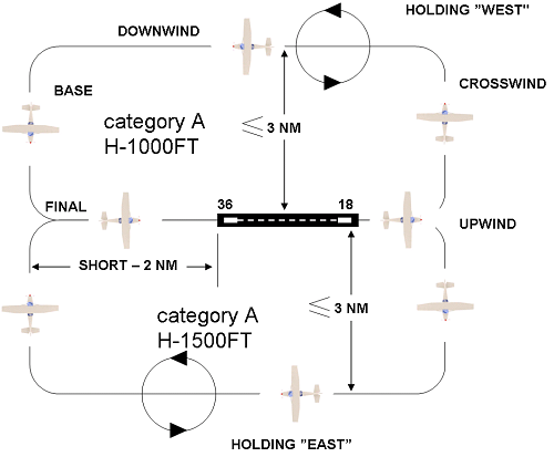
3.2.1.3 For RWY 36, the aircraft shall follow the left- (ALT 1000 ft or below) or right- (not below ALT 1500 ft) hand visual traffic circuit.
3.2.1.4 For RWY 18 the aircraft shall follow the left- (not below ALT 1500 ft) or right- (ALT 1000 ft or below) hand visual traffic circuit.
3.2.1.5 A left- or right-hand visual traffic circuit is assigned by a RIGA TOWER controller depending on the traffic situation or meteorological conditions in the vicinity of the aerodrome.
3.2.1.6 A deviation from the standard traffic circuit may be requested and is allowed only if ATC clearance is given.
3.2.2 Procedures for IFR training flights
3.2.2.1 Training flights by IFR can be executed by Aircraft Speed Approach A, B or C Category (see EVRA AD 2.24.16).
3.2.2.2 Deviation from the standard IFR procedure may be requested and is allowed only if ATC clearance is given. Radar vectoring will be provided.
3.2.2.3 Visual manoeuvre for IFR flights
3.2.2.3.1 Before departure or at any stage of a standard IFR procedure, a pilot can request a visual manoeuvre.
3.2.2.3.2 An IFR training flight may be cleared to execute a visual manoeuvring approach if:
- the pilot can maintain visual reference to the terrain and make a request to perform the next approach as visual and
- the reported ceiling is 1500 ft or above, or the pilot reports that the meteorological conditions are such that, with reasonable confidence a visual approach and landing can be completed.
3.2.2.3.3 Visual manoeuvring should be executed inside the limits of the circling area (Figures 2 and 3).
Visual manoeuvre for RWY 36
Figure 2.

After take-off, touch-and-go or low approach:Climb straight ahead, passing 600 ft, turn left climbing to 1000 ft or 1500 ft. If visual contact with the terrain is lost during manoeuvring, turn towards the runway to execute the go-around over the runway. Report to RIGA TOWER that the missed approach procedure will be executed, as published in EVRA AD 2.24.13 ILS RWY 36.
Visual manoeuvre for RWY 18
Figure 3.
After take-off, touch-and-go or low approach:
Climb straight ahead, passing 600, ft turn right climbing to 1000 ft or 1500 ft. If visual contact with the terrain is lost during manoeuvring, turn towards the runway to execute the go-around over the runway. Report to RIGA TOWER that the missed approach procedure will be executed, as published in EVRA AD 2.24.13 ILS RWY 18.
3.3 ATC procedures for IFR flights
3.3.1 The pilot shall make a request for the manoeuvre to the RIGA TOWER controller in flight:
a.executing the visual manoeuvre - before turning onto the base leg, using the following phrases:
"Continue visual manoeuvre:
- touch-and-go;
- low approach;
- full stop;
- next flight via standard training IFR procedure;
- next flight request radar vectoring"
b.executing standard IFR procedure - after passing RIA DVOR/DME using the following phrases:
“Continue standard procedure:
- touch-and-go;
- low approach;
- full stop;
- next flight as visual;
- next flight request radar vectoring.”
3.3.2 Before departure, on the ground, the pilot can make a request to the RIGA TOWER controller for:
- the visual manoeuvre or;
- standard IFR procedure or;
- radar vectoring.
3.3.3 If ATC requires the aircraft to discontinue the approach, the phrase " BREAK OFF APPROACH" is used and supplemented with further instructions as necessary.
3.3.4 If ATC requires the aircraft to execute the missed approach procedures, as published in AIP Latvia, the phrase “GO AROUND, FOLLOW MISSED APPROACH PROCEDURE" is used and supplemented with further instructions, as necessary.
3.4 ATC procedure for VFR training flights
3.4.1 Before turning base, the pilot shall make a request for the manoeuvre to the RIGA TOWER controller using the following phrases:
“Continue visual traffic circuit:
- touch-and-go;
- low approach;
- full stop.”
4. LOW VISIBILITY PROCEDURES (LVP)
4.1 Runways and associated equipment
RWY 18 and RWY 36 are approved for CAT I/II approaches and for LVTO in RVR conditions of not less than a value of 250 m.
ILS category II, DME 18/36, FFM 18/36, DME RIA are available to RWY 18 and RWY 36 subject to serviceability of the required facilities.
4.1.1 Advanced Surface Movement Guidance and Control System (A-SMGCS)
Surface movement radar is available to ATC.
Failure in A-SMGCS will degrade LVP so that only CAT I approaches when RVR is not less than 550 m and take-offs when RVR is not less than 450 m may operate on RWY 18/36.
4.1.2 Approach spacing
In order to maintain protection of the ILS, no vehicle or aircraft shall penetrate/infringe ILS critical and sensitive areas. In order to fulfil this requirement, more than 8 NM spacing between arrivals will be used.
4.2 Criteria for activation of LVP
Standby for low visibility procedures is prompted by ATC when RVR is 700 m or less or the ceiling is 200 FT or less.
Low visibility procedures are effected by ATC when RVR is 550 m or less or the ceiling is 150 FT or less. Low visibility procedures are cancelled by ATC when RVR is greater than 700 m and a continuing improvement in RVR conditions is anticipated, and the ceiling is greater than 250 FT.
Pilots will be informed when low visibility procedures are in operation by ATIS or radio.Pilots will be informed over radio when LVP are cancelled.
Low visibility operations will be suspended as a result of certain equipment failure/degradation modes or procedure breaches.
ATC procedures do not allow for snow clearing on the manoeuvring area when LVP are effected but do allow for limited snow clearing on the manoeuvring area when standby for LVP is prompted.
4.3 Description of ground marking and lighting
4.3.1 RWY exit
Taxiways A, B, C, Y, D, E and G are equipped with taxiway centre line lights and may be used for RWY exit.
Back track procedures shall not be allowed after landing unless it shall be the only option for vacating the runway safely.
Centre line lights on all exits are colour coded green/yellow until the runway-holding position (100 m from RCL).
Pilots shall not call “runway vacated” until the aircraft has completely passed the end of the green/yellow colour coded taxiway centre line lights.
4.3.2 RWY entry
Category II holding points at all RWY entries are equipped with internally illuminated sign boards, runway guard lights and red stop bars. Aircraft shall stop and hold short of an illuminated stop bar until the stop bar is switched off and clearance to continue is received from ATC.
When low visibility procedures are in force, the available RWY entries are limited to:
- CAT I/II holding position on TWY G (or TWY E if TWY G not AVBL) for RWY 18;
- CAT I/II holding position on TWY A (or TWY B if TWY A not AVBL) for RWY 36.
4.3.3 Taxiing
Taxiing is restricted to taxiways equipped with centre line lights as indicated on the aerodrome chart. On receiving taxi clearance, aircraft must only proceed when a green centre line path is illuminated. In the event of failure of the taxiway lights, aircraft are only to taxi in the direction of a “follow me” vehicle.
Taxiing operations shall be carried out in accordance with RIGA TOWER instructions/information and through the opportune use of the established Intermediate Holding Positions (IHP).
The following IHP, equipped with yellow intermediate holding position lights, are available for aircraft movements:
- on TWY F: IHP at intersections with TWY E, TWY D, TWY C (all bidirectional), IHP at junction with TWY A, TWY B and de-icing pad DS (direction South), IHP at junction with TWY G and de-icing pad DN (direction North) as well as IHP F1 and IHP F2;
- on TWY G: IHP G1, G2 (both direction North);
- on TWY A: IHP A1, A2 (both direction South);
- on TWY E, TWY D, TWY C, TWY B: ITHP before intersection with TWY F (direction East).
Taxiing aircraft shall observe the ground speed limit of 15 knots.
4.4 Take-off
Low visibility take-off with LOC guidance is not available.
5. SIMULATED CAT II APPROACHES IN CAT I CONDITION
5.1 This procedure is intended for operators, which have obtained the standard category II (CAT II) approval by their respective authorities.
5.2 ILS sensitive areas are not protected for the Simulated CAT II approach at Riga Aerodrome.
5.3 The pilots, who wish to practise the Simulated ILS CAT II approach in the above mentioned condition, have to request this on initial contact with RIGA APP using the phrase: "Request simulated CAT II approach".
This request has to be made timely so the APP and TWR controllers can establish appropriate separation.
5.4 The permission will be granted depending on the traffic situation or ground equipment availability.
5.5 The pilot should inform Riga TOWER controller about alternative actions in case of discontinuation of the Simulated CAT II approach.
5.6 Riga TOWER controller will inform the pilot about ILS sensitive areas penetration, if known, and about ILS and lighting system degradation
EVRA AD 2.23 ADDITIONAL INFORMATION
1. BIRD CONCENTRATIONS IN THE VICINITY OF THE AIRPORT
The aerodrome is located in an intense bird migration path.
Spring migration (March – May). Main migration path - NNE - NE. The bird concentrations are observed in the following places: the Svetes flood-land (waterfowl migration halt point) located 28 km Southwest from the aerodrome, the Cenas moorland located 10 km from the aerodrome and the Babites lake located 8 - 18 km from the aerodrome. As the migration starts, dangerous concentrations of birds take place early in the morning and late in the afternoon at the heights of 0 - 3000 ft (0 - 1000 m) AGL.
Autumn migration (August – October). Main migration path – SW. The main waterfowl migration halt point is located West of the aerodrome (the Babites and the Kaniera lakes and the Kemeru moorland). The autumn migration over the aerodrome is less intense.
2. SAFETY ON APRON
2.1 All crew members and technical personnel must wear high visibility clothing (a vest or uniform) when walking airside.
2.2 All airside personnel, including crews, are encouraged to act responsibly if they notice any Foreign Object Debris (FOD). Best practice is to pick up the detected debris and dispose of it in the nearest disposal bin. It is also strongly recommended that flight crew and technical crew ensure they are aware of all tools and hardware used airside to avoid incorrect FOD incidents.
2.3 For safety, it is recommended that an airside car or bus is used whenever necessary because there are no designated walkways on the apron.
3. 180 DEGREE TURNS ON RUNWAY
During winter when the declared cleared width of the runway is below 45 metres, aircraft longer than 30 metres will not be allowed to perform 180 degree turns on the runway to avoid potential runway excursions.
4. AERODROME ACCEPTED DEVIATIONS FROM THE APPLICABLE REQUIREMENTS AND SPECIAL CONDTITIONS
4.1 DEVIATIONS
|
Applicable requirement |
Deviation description |
|---|---|
|
CS ADR-DSN.E.355 Strength of aprons |
The PCN indicator of the pavement bearing strength calculated on the assumption of a 10-year service life does not comply with the maximum ACN values for some aircraft that are intended to be operated on the relevant aerodrome parts for aircraft stands 226, 401, 402 and portion of an aircraft stand taxilane E and for aerodrome area Z3 which is used for aircraft maintenance and mainly engine testing. |
|
CS ADR-DSN.J.480 Precision approach runways |
For runways 18 and 36, approach obstacle limitation surface is penetrated by objects (vegetation, trees, forest, building, telecommunication antenna) which are not navigation aids. |
|
CS ADR-DSN.J.485 Runways meant for take-off |
For runways 18 and 36, take-off climb obstacle limitation surface is penetrated by objects (vegetation, trees, forest) which are not navigation aids. |
|
CS ADR-DSN.M.710 Taxiway centre line lights |
Taxiway centre line lights are not provided on aircraft stand taxilanes R, S, Q, T, P, C, U1, U, V, W at the aerodrome. |
|
CS ADR-DSN.M.750 Apron floodlighting |
On aprons 2 and 4 the average illuminance on taxilines C, Pand E1 does not reach 50% of the average illuminance of the aircraft parking areas. |
|
CS ADR-DSN.M.765 Aircraft stand manoeuvring guidance lights |
Aircraft stand manoeuvring guidance lights are not provided on aircraft stands. |
|
CS ADR-DSN.Q.850 Lighting of other objects |
Vehicles driving in the manoeuvring area are equipped with flashing lights that comply with the UN-ECE R65 standard and thus do not comply with the specified specifications. |
|
CS ADR-DSN.T.910 Equipment frangibility requirements |
Objects that are considered necessary for air navigation purposes but cannot be considered fragile (including the ILS GP antenna and its service container) are located on the runway strip. |
4.2 CASES OF EQUIVALENT LEVEL OF SAFETY
|
Applicable requirement |
Deviation description |
|---|---|
|
CS ADR-DSN.D.240 Taxiways general |
On a rapid exit taxiway D the outer wheel of the DH8D (IATA code - DH4) or Bombardier Dash 8-Q400 aircraft main landing gear is at a distance of less than 4 meters but not less than 3.37 meters from the taxiway edge when the cockpit of the aircraft remains over the taxiway centre line markings. |
|
CS ADR-DSN.D.245 Width of taxiways |
Taxiway D having width 18 meters instead of 23 meters may be used by DH8D (IATA code - DH4) or Bombardier Dash 8-Q400 aircraft which has a distance between the outer wheels of the main landing gear 9.6 meters and which is the only aircraft with a distance between the outer wheels of the main landing gear exceeding 9 meters, which complies with the limitation published in the AIP that the taxiway D may be used by aircraft with a wingspan of less than 36 meters. |
|
CS ADR-DSN.E.365 Clearance distances on aircraft stands |
On aircraft stand 314 which may be used by up to code C aircraft the minimum clearance of 4.5 meters between the aircraft departing the aircraft stand and an object is not provided due to a 1.3 m high object (stationary aircraft servicing equipment – a fixed power supply unit or GPU transformer unit) being located 21.8 m from the alignment line. An equivalent level of safety is provided by standard marshalling signals. |
|
CS ADR-DSN.L.580 Intermediate holding position marking |
Intermediate holding position marking is not provided on the exits from the remote de-icing/anti-icing areas DN and DS. An equivalent level of safety is provided by standard marshalling signals and selectively switchable taxiway centreline lights. |
|
CS ADR-DSN.M.740 De-icing/anti-icing facility exit lights |
The exit boundaries of remote de-icing/anti-icing areas DN and DS adjoining taxiways G and A are not designated with de-icing/anti-icing facility exit lights meeting the applicable requirements. An equivalent level of safety is provided by standard marshalling signals and selectively switchable taxiway centreline lights. |
|
CS ADR-DSN.M.771 No-entry bar |
An inset no-entry bar is not provided on taxiway D which is used for aircraft traffic only as an exit taxiway or one way only rapid exit taxiway. An equivalent level of safety is provided by a configuration of mandatory instruction signs and marking and taxiway centreline lights, that impose a permanent ban on the aircraft traffic in the opposite direction to the direction of the rapid exit. |
|
CS ADR-DSN.N.775 General [on aerodrome signs] |
The area of the red background on the “No entry” signs is 2/3 of the required area, i.e. the width of the signs is 80 cm instead of 120 cm. Such signs are installed together with the mandatory instruction marking "NO ENTRY" on the one-way rapid exit taxiway D and on the remote de-icing/anti-icing area DN and DS exits DS, DS1, DN, DN2 and DN1 adjoining taxiways A and G. |
4.3 SPECIAL CONDITIONS
|
Applicable requirement |
Deviation description |
|---|---|
|
CS ADR-DSN.L.595 Apron safety lines |
Wing tip clearance line between aircraft stands 292 and 293 is not continuous in length. A special condition is provided by marshalling signals. |
|
CS ADR-DSN.N.785 Information signs |
RWY exit sign on RWY18 for TWY C is located at 36 m prior to the RWY exit point in line with the position to the point of tangency of TWY and RWY exit sign on RWY36 for TWY Y is located at 35 m prior to the RWY exit point in line with the position to the point of tangency of TWY. |
EVRA AD 2.24 CHARTS RELATED TO THE AERODROME
|
1. Aerodrome chart — ICAO
|
|
2. Aircraft Parking/Docking Chart — ICAO
|
|
3. Aerodrome Ground Movement Chart — ICAO
|
|
4. Aerodrome Obstacle Chart — ICAO Type A (for each runway)
|
|
5. Aerodrome Obstacle Chart — ICAO Type B - NIL
|
|
6. Aerodrome Terrain and Obstacle Chart — ICAO (Electronic)
|
|
7. Precision Approach Terrain Chart — ICAO
|
|
8. Area Chart — ICAO (departure and transit routes) - NIL
|
|
9. Standard Departure Chart — Instrument (SID) — ICAO
|
|
10. Area Chart — ICAO (arrival and transit routes) - NIL
|
|
11. Standard Arrival Chart — Instrument (STAR) — ICAO
|
|
12. ATC Surveillance Minimum Altitude Chart — ICAO
|
|
13. Instrument Approach Chart — ICAO
|
|
14. Visual Approach Chart — ICAO
|
|
15. Bird concentrations in the vicinity of the aerodrome - NIL
|
|
16. Instrument Approach Chart for Training Flights — non-ICAO
|
|
17. Arrival and Departure Route Chart — non-ICAO - NIL
|
